


Marine Safety Signs – Design and Installation, Code of Practice in Compliance with ISO 24409 |
|
Introduction This article is on ISO 24409 – Ships and marine technology – Design, location and use of shipboard safety signs, safety-related signs, safety notices and safety markings. This standard was initially published in 2010. That initial publication resumed to its Part 1: Design Principles which was complemented in 2014 with the publication of Part 2: Catalogue and Part 3: Code of practice. ISO 24409 aims to establish a standardized signage system that communicate effective safety information to people who travel and work on-board ships and other marine installations. It is therefore a highly relevant standard for the Marine & Offshore industries as it supplements the already existing requirements of SOLAS Conventions, IMO Resolutions and ISO 17631 on safety signs that are to be used on-board. As previously mentioned, ISO 24409 is divided in 3 parts: Part 1: Design Principles, Part 2: Catalogue and Part 3: Code of practice. In this article we will mainly focus on Part 1 and Part 3 as Part 2 is basically the list of safety signs that shall be used on-board. ISO 24409 Part 1 sets the design principles that are to be followed in the development of marine safety signs. Those principles are consistent with other safety sign standards, namely ISO 7010, already in use for other applications. ISO 24409 Part 3 provides guidance on safety signage systems for the escape routes, fire-fighting and life-saving equipment. These guidelines include: adequate symbols and supplementary text, sizes of the signs and installation locations and installation heights. |
|
Design principles As we may be aware, a safety signage system is a communication language and like any other language it has its specific rules, the safety signs design principles, that must be followed and should be intrinsic to its users in order to assure that the message conveyed by marine safety signs is understood by passengers, visitors, associated crew and specialized, trained personnel. The color and the geometric shape of marine safety signs are identified as the starting point elements on safety signs development and are crucial in the transmission of the intended message. On this matter ISO 24409 recurs to what has been standardized by ISO 3864: - red color rectangular or square shaped signs must be used for fire-fighting equipment; - green color on rectangular or square shaped signs are for evacuation or emergency equipment signs; - prohibition signs will have a red circular shape and a cross bar over its graphic symbol; - warning and hazard signs will be designed with a black colored tringle on a yellow background; and - mandatory action signs will be designed on a blue circle. The table below sums up ISO 3864 definitions on safety signs in terms of their color and geometric shape as used in ISO 24409: 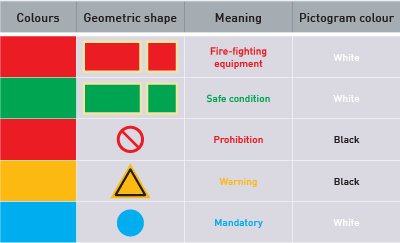 With the colors and geometric shapes specified, the standard focus on the meaning and the function of each safety sign stating that these must be unambiguous. Therefore, safety signs must have an image content which graphical symbol can be composed with a referent or a referent and a determinant: 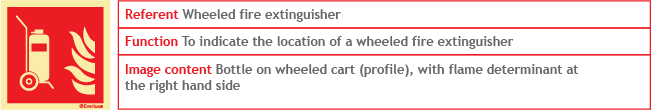 The safety sign shown in the example above the referent used is a wheeled fire extinguisher as the function of this safety sign is to indicate the location of a wheeled fire extinguisher. The image content of this safety sign is a bottle on a wheeled cart, shown on profile layout, with a flame determinant at the right hand side. Determinants are used in conjunction with other graphical symbols to improve the comprehension of a safety sign. Another typical example of a determinant is the first aid cross used on emergency equipment safety signs: 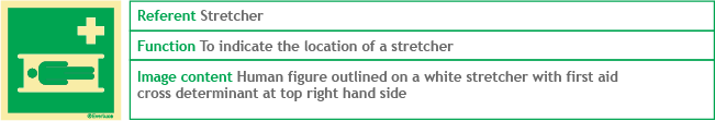 |
|
Categories of Safety Signs This takes us to the safety sign categories defined by the standard. From the table above we can immediately identify 5 main safety sign categories but ISO 24409 specifies an additional 2 categories of safety-related signs and another 3 of safety markings. We therefore have the following shipboard safety sign categories: Fire-fighting equipment signs (FES) – shipboard safety signs that communicate the use and location of fire-fighting equipment. 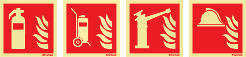   Means of escape signs (MES) – safety signs for escape route identification on-board. 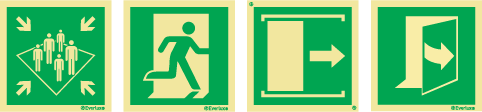 Prohibition signs (PSS) – safety signs to restrict or prohibit the movement and actions of persons on-board.  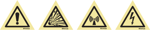 Mandatory action signs (MSS) – safety signs to be used for mandatory notices and instructions on-board.  Mimic signs (SMS) – mimic signs are safety-related signs that have the purpose of informing passengers of their exact location on-board, indicating their escape routes and of providing specific safety instructions. In order to accomplish this purpose, Mimic signs should be displayed in passenger ships in or at the entrance of conspicuous passenger areas, within or close to passenger stairway enclosures, at internally located assembly stations, and inside each passenger cabin. 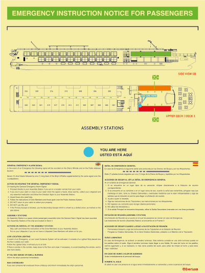 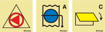 Safety markings – used to mark areas with relevant safety information. 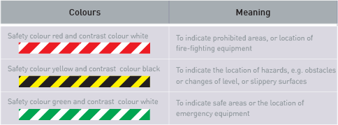 |
|
Supplementary Signs, Combination Signs and Multiple Signs Supplementary signs provide complementary information and will extend the safety message communicated by the referent of a given safety sign. There are supplementary explanatory signs, supplementary directional arrow signs and supplementary identification signs. When a safety sign is used in conjunction with a supplementary sign, that conjunction becomes a combination sign. The example below uses a fire extinguisher sign together with several supplementary signs: 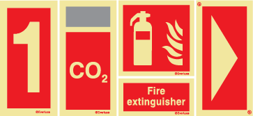 When a text supplementary sign is used then it should use the languages that are appropriate to the service of the ship and the working language on-board the vessel as illustrated in the example below using a fire extinguisher identification supplementary sign with English and Russian text.  Directional arrow signs should always be used in conjunction with safety signs and never be used on its own. 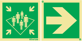 When several combination signs are used in conjunction they become a multiple sign. In this example we have the general mandatory and general prohibition safety signs used with text supplementary signs which altogether compose a multiple sign. 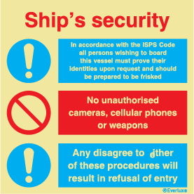 |
|
Safety Signs sizes and respective viewing distances The viewing distance of a safety sign is related with its size. ISO 24409 uses the viewing distance formula given in Annex A of ISO 3864-1:  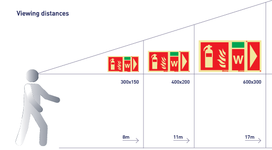 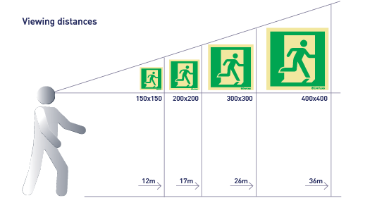 |
|
Illumination and marking of safety signs Safety signs in general and marine safety signs specifically will only convey their safety messages effectively as long as they will be visible under any circumstances namely during a blackout or fire on-board. Photoluminescent safety signs are the only signs that can assure visibility under any situation and therefore ISO 24409 specifies that Photoluminescent safety signs shall be used (applicable for FES, EES, LSS, and MES signs) if they are not illuminated by the emergency lighting conditions or in areas where emergency lighting is not required. Photoluminescent safety signs must have the same performance as any Low Location Lighting (LLL) system installed on-board according to ISO 15370 or comply with the requirements of ISO3864-4. In fact, not all photoluminescent safety signs have the same effectiveness in terms of luminance performance and therefore ISO 24409 requires that every shipboard safety sign carries the manufacturer brand, have the luminance decay properties and have their item code printed on. Marking the signs with this information together with third party certification provides greater peace of mind to safety officers ensuring them that the signs they are sourcing and installing in their vessels will indeed be effective in case of an emergency. Everlux complies with all of these ISO 24409 requirements. For your convenience, below you will find a comparative table with the Everlux luminance properties and an illustration on the traceability markings on every Everlux sign: 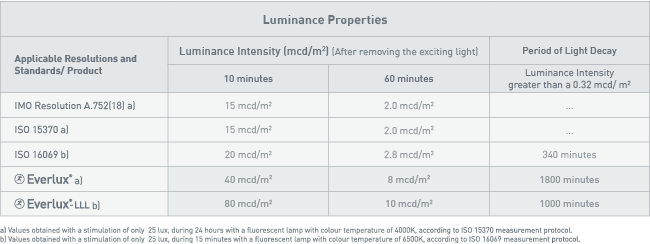 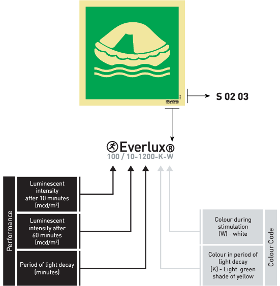 |
|
Escape route signing system The objective of the escape route signing system is to ensure that a sign or a series of signs is provided and placed so that a person is directed along the escape route from any space within a ship or a marine installation towards an assembly station or embarkation station. The signing system should be designed based on the means of escape plan, assembly station plan, and lifesaving plan. It should provide simple information that will make it easy to identify the means of escape provisions, allow people to escape with minimum assistance and avoid possible points of confusion. 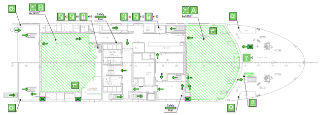 Exit signs should be installed in every exit doors and hatches from machinery spaces, service spaces and accommodation areas that lead to escape routes. To aid with the orientation within the ship deck identification signs should be conspicuously installed at stair landings and lift lobbies and reproduce the deck numbering used in the safety plans. All embarkation stations should be sequentially numbered from fore to aft using odd numbers on the starboard side and even numbers at the port side: 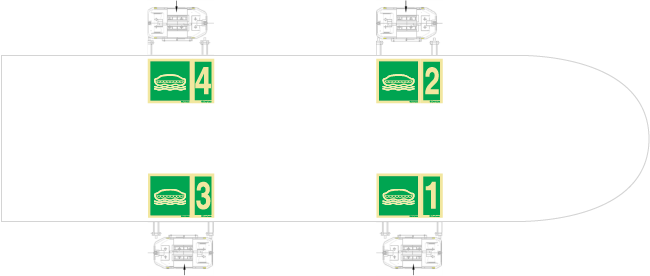 Following the same logic, all assembly stations should be sequentially lettered from fore to aft initiating the sequence with the letter "A” from starboard side to port side: 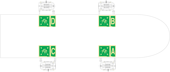 The escape route throughout the vessel should be identified with assembly station signs. This should be placed in areas such as stairways, corridors, entrance halls, and on outside decks nearby doors with access to the assembly stations or to the egress route to the assembly stations. In cases of vessels with multiple assembly stations, assembly stations signs with the respective identification letter supplementary signs must be used at the deck level of an assembly station:  In passenger ships the assembly station signs should be installed in evacuation routes through enclosed stairways which will provide fire shelter to evacuees from the level where they start to evacuate all the way to the assembly station. Whenever the assembly stations are in a different location of the embarkation stations, the signing system should include egress route identification signs marking unambiguously the evacuation route from the assembly stations to the embarkation stations. This should be done with the adequate survival craft directional signs. For example using the signs in the example below for lifeboats, davit-launched life-rafts and evacuation slides supplemented with directional arrows: 
|
|
Location and installation height of escape route signs Escape route signs take priority over any other signs. These should be installed at consistent intervals of up to 15m in order to make it easier for evacuees to predict the location of the next evacuation sign. Escape route signs should be installed at the center line over the doors at a height between 2.0m and 2.5m from the deck to the base of the sign in order to assure visibility from any foot traffic area. The escape route signs that are to be installed on bulkheads should be installed between 1.5m and 2.0m. As far as it is possible installation heights should be kept throughout the escape route. 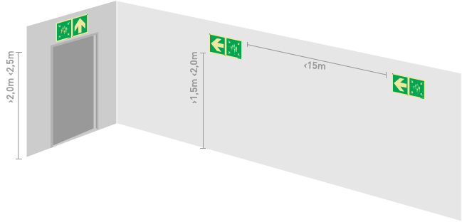 On passenger vessels if the escape routes to the assembly stations and embarkation stations are not accessible to mobility impaired people then the alternative escape route for mobility impaired people should be marked unambiguously and supplemented with the international symbol for accessibility in compliance with ISO 7001.  |
|
Fire-fighting equipment and live-saving appliances signing system Fire-fighting equipment and lifesaving appliances should also be marked unambiguously using the respective signs as specified by ISO 24409. The standard doesn’t gives a specific installation height for these category of signs stating instead that the signs should be fitted at or near the equipment at a height which is suitable for the location of the equipment. See below one example of installation heights for each of these sign categories: 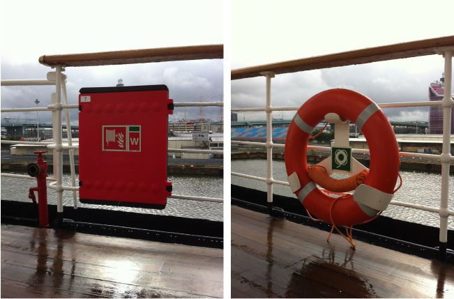 Furthermore, the location of the fire-fighting devices and systems should be marked with SIS signs containing the respective Fire Control Plan symbols. 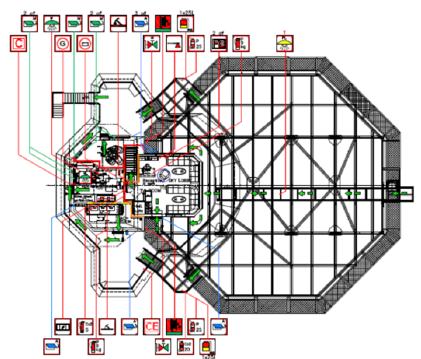 |
|
Documentation of safety signing system, Inspection and maintenance of signs The signing system installed on-board should be documented with the following information: - Safety signage plan as installed updated as necessary to reflect any changes made; - Safety signs list including every sign which has been installed, their respective item codes and main technical properties; - Identification of the supplier and applicable certifications; - Maintenance log. This documentation should be kept on-board and be used for training and maintenance purposes. The maintenance of the signing system should include regular visual inspections in order to identify any cleaning or replacement needs. We hope that you found this article to be helpful not only in summarizing the main requirements of ISO 24409 but also to help you to improve your understanding on how to manage your on-board safety signage systems. Everlux will shortly start updating its signs as per ISO 24409. In the meantime, do not hesitate to contact us if you have any questions on this article or on safety signs from supply through installation, inspection and documentation. We look forward to hear from you at commercial@everluxmaritime.com. |
-
PRODUCTS
- Means of Escape Signs (MES)
- Emergency Equipment Signs (EES)
- Other Safe Condition Signs
- Life-Saving Appliance Signs (LSS) - IMO Signs/ Marine Safety Signs
- Fire-fighting Equipment Signs (FES)
- Signs for Elevators and Lifts
- Fire Control Plan Signs For Shipboard Use (SIS)
- Damage Control Plan Signs
- Low Location Lighting (LLL) System
- Panoramic Signs
- Marking Strips
- Prohibition Signs (PSS)
- Hazard Warning Signs (WSS)
- Mandatory Action Signs (MSS)
- Multipurpose Combination Signs
- Information Signs
- ISPS Code Signs
- Infection Prevention and Control Safety Signs
- Safety Signs for Super Yachts
- Offshore Wind - Safety Signs
- Water Safety Signs
- Temporary Tie Tags
- SOLAS TAPE
- Pipe Content Identification Tapes
- Anti-Splashing Tape
- IMDG Code
- Safety Awareness and Training Procedures
- General Safety Awareness Notices
- Escape Plan Signs | Mimic Signs
- Fire Control and Safety Plans
- Everlux Frames
- Everlux Adhesive
- SERVICE
- BECOME A DISTRIBUTOR
- TECHNICAL INFORMATION


